Soldering Guidelines
A primary consideration in the soldering of high-voltage ceramic capacitors is avoiding thermal shock. The micro-crystalline structure of ceramic materials makes them brittle and susceptible to failure if the components are heated or cooled too quickly. It is also important to avoid mechanical shocks, so proper handling guidelines are the first step in a successful soldering process.
Handling High Voltage Ceramic Capacitors
Because of their size, high-voltage ceramic capacitors should be packaged such that each component has its own secure spot, rather than the bulk shipment approach often used for smaller form factor capacitors. This helps prevent mechanical shocks to the ceramic, which could be significant if a component that size is free to rattle around. For handling individual components, metal tweezers should be avoided, because the hard, sharp edges can scratch the surface or create high-stress intensity points that contribute to fracturing of the ceramic. Plastic tweezers are recommended.
Soldering Processes for High Voltage Ceramic Capacitors
Three main categories of the solder attachment process are hand soldering, infrared / convection oven, and vapor phase reflow. Hand soldering is common for custom, low-volume products. This allows process flexibility, but it is also the hardest to control. The thermal characteristics are a function of the human factors in the process. An infrared / convection oven moves the parts through an oven with the process (time and temperature) programmed in and regulated by infrared or convection heating, so it can be controlled much more tightly. The atmosphere can also be controlled, and a nitrogen ambient is commonly used to prevent oxidation. Vapor phase reflow uses the process of vapor condensation in the reflow chamber to transfer heat during the process, and many of the general process considerations are the same as for infrared or convection ovens.
Pre-heating
An important step for any soldering process is to pre-heat the component and the board to avoid a dangerous thermal shock when the solder is reflowed. An advantage to a reflow oven is that pre-heating can be programmed into the reflow profile. For hand soldering, the parts can be heated in a conventional thermal oven, but this creates more handling processes. Whatever the process, pre-heating to within 50-60 degrees C of the reflow temperature is a good guideline.
Reflow Profiles
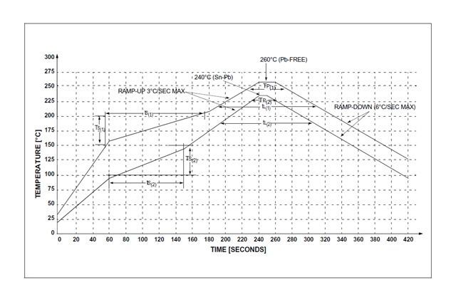
There is a trade-off between slow temperature ramps and process throughput. A common guideline is about 2 seconds per degree C when heating, but often somewhat faster in the cooling phase. A slower ramp reduces the thermal shock, and this is one process variable to consider when optimizing the process for a reliable solder joint. Another process variable to control is the dwell time at the reflow temperature, and 10-30 seconds is a common guideline. Below is a general solder reflow time/temperature profile from JEDEC standards that illustrate the numerous variables to consider when optimizing a solder attachment process.
In summary, there are many issues to consider when developing a solder attachment process for high-voltage capacitors. A thorough understanding of the issues presented here is needed to ensure a robust process.