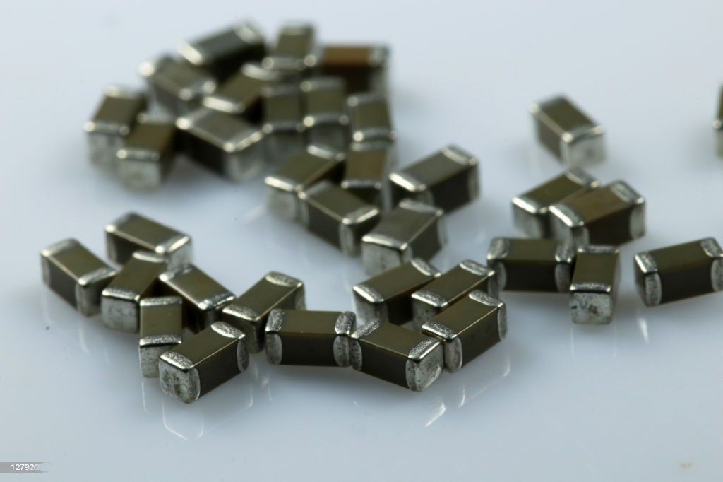
Providing the Ceramic Capacitors You Need
Founded in 1968, Circuit Functions Inc. (CFI) has grown to be a respected provider of ceramic capacitors worldwide. All CFI products are made in the USA at our facility in Carson City, Nevada. We manufacture a variety of multilayer ceramic capacitors which include high-voltage chip and leaded capacitors, high-temperature chip and leaded capacitors for both low and high-voltage applications, surface mount capacitors, and custom capacitors tailored to meet the specific needs of our customers. Get in touch and see how we can meet your needs!

Markets Served
CFI capacitors support a variety of applications and markets including aerospace and avionics, down-hole drilling, oil exploration and other high-temperature electronics, power supply, and a wide range of commercial and industrial applications. Our team is always ready to assist.
High-Quality Ceramic Capacitors
With some of the best lead times in the industry, CFI can often provide the desired components before your production deadlines. We strive to match your particular needs and standards by offering high-quality capacitors whether it be high voltage, high temperature, surface mount, or custom capacitors to your specification. Contact Circuit Functions if a part number is needed that isn’t on our product list so we can find one that meets your requirements and provide you the capacitors you

Rigorous Quality Control
Quality control is something we take very seriously. CFI manufactures capacitors for some of the world’s most demanding applications and we are known for our commitment to quality and reliability. We have implemented stringent quality control procedures to guarantee that every capacitor we manufacture lives up to our high standards. We have a reputation for manufacturing high-quality dependable capacitors that satisfy the demands of our clients across a variety of sectors because of our dedication to quality.
Find out how we can help you!
Wide Array of Customizable Options
To fulfill your unique demands, we provide a wide range of customizable options. In addition to our product line, custom sizes, values and voltages are available to fit your specifications. Our team is committed to offering you a unique solution that is catered to your requirements. Let us help you by getting in touch with us to discuss your ceramic capacitor needs.

Knowledgeable Technical Support
Quality control is something we take very seriously. CFI manufactures capacitors for some of the world’s most demanding applications and we are known for our commitment to quality and reliability. We have implemented stringent quality control procedures to guarantee that every capacitor we manufacture lives up to our high standards. We have a reputation for manufacturing high-quality dependable capacitors that satisfy the demands of our clients across a variety of sectors because of our dedication to quality.
Find out how we can help you!
FREQUENTLY ASKED QUESTIONS
Why should I choose Circuit Functions Inc.?
Circuit Functions Inc. is a high-voltage ceramic capacitor manufacturer with more than 50 years’ experience in the industry. Our MLCC’s are designed to operate reliably and efficiently in the most demanding applications. CFI ensures fast, reliable delivery times with competitive pricing. Manufacturing lead times are generally 6 weeks or sooner. At CFI, we pride ourselves on our ability to work with our customers to meet their unique application requirements. When our customers succeed, we do too. We value the trust that our clients place in us and that is why we have been partnering with many of our customers for over 30 years.

